VMware NSX Logical Switch and DLR Configuration
VMware NSX Logical Switch and DLR config via GUI-API – Logical switches are broadcast domains which basically allow you to create a business units/contexts out of VM’s , and allows you to control whether the VMs placed in those business context can talk to each other.
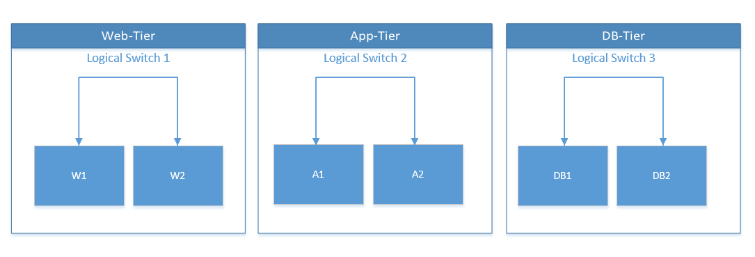
For example lets consider a scenario of a typical web application deployment, it consists of the “Web-Tier”, “App-Tier” and the “DB-tier”. creating logical switches for each of these tiers allows the VMs within these tiers to talk to each other, but not across the tier’s.
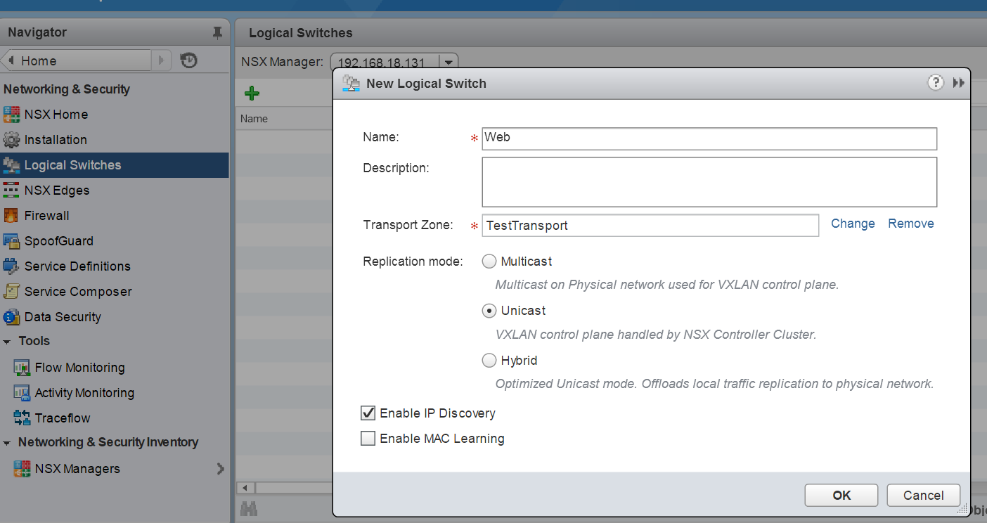
Next lets create our Logical Switches, creating this via the GUI is straightforward, head over to the logical switches tab and create the switch.
Next lets explore how to this via API calls. The NSX API Guide contains details on how to create this via API call.
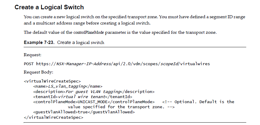
You can follow some of my previous posts on how to invoke this API call via powershell and automate the creation of Logical Switches.
Once you create the Logical Switches you can tag the VMs which should be part of the logical switch. For a VM with 10 vnics you would need to individually select each of the vnic to associate it with the Logical switch.
Using the GUI, you will need to click on add virtual machine and specify the vnics of the VM’s which you want to be part of this logical switch.

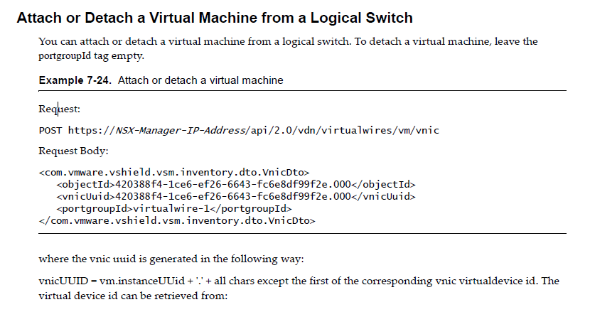
you can also invoke this via API
Once you have created the Web,App and DB tier logical switches the VMs tagged within the logical switches would be able to talk to each other, next what we need is that the vms across the logical switch should talk to each other, well to solve this we would use the DLR ( Distributed Logical Router).
The Distributed Logical router helps in distributing every interface through the kernel so that it gets replicated across every host, the vm when it tries to communicate it will always be able to get to its default gateway and will be able to find the destination after the first hop as the DLR interfaces are replicated across the hosts.
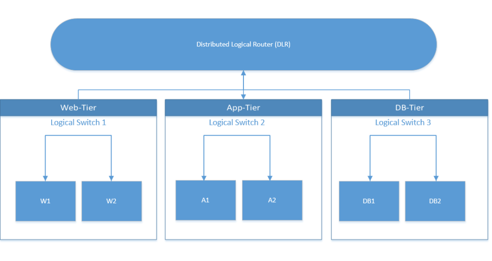
So once we have the DLR in place, our visio diagram would look something like below.
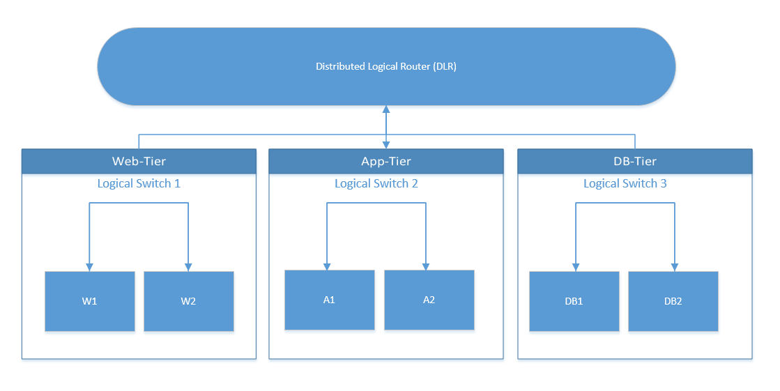
The DLR would facilitate the communication between the VMs in each tier.
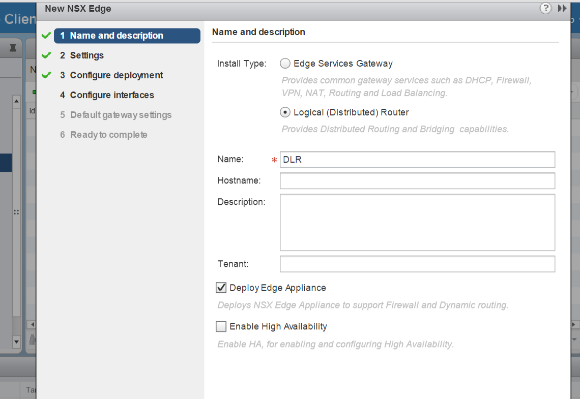
Next lets create the DLR, to create the DLR via GUI, click on the “NSX Edges” tab, and click on new NSX edge, feed in the required parameters.
One of the most important section is where you configure the interfaces for the DLR, these interfaces would get replicated across the hosts, in the interface creation wizard you will be also asked which NSX logical switch should be connected to the interface.
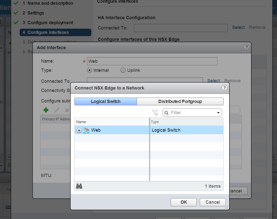
As you can see i selected the Web logical switch, this effectively means that this interface settings will be replicated across all the hosts in my cluster.
We can follow the similar steps to create network interfaces for the other logical switches App,DB.
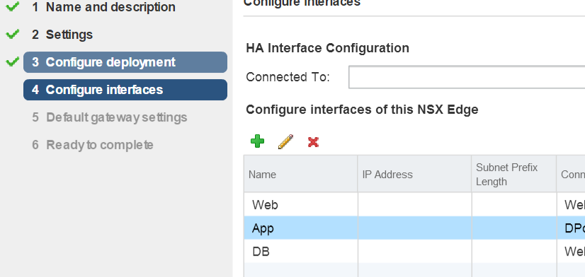
Once the above steps are completed, you can confirm that all works good, if you are able to ping the VMs across the Web/App/DB tier

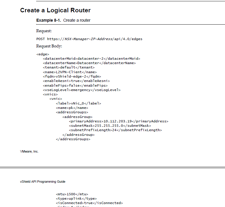
Again, you can invoke this via API too, i have shown below a section of the extract from the API guide.
i hope you enjoyed this blog post on “VMware NSX Host Preparation and configuration” using PowerShell and found this information useful.
Do check out some of my other Posts on NSX


Pingback: VMware NSX Host Preparation with PowerShell
Pingback: VMware NSX Controller Cluster creation with PowerShell
Pingback: VMware NSX PowerShell Installation
Pingback: VMware NSX : Why we need it in SDDC. -Virtualize & Automate-
Pingback: Getting Started with PowerNSX - PowerShell Module for NSX
Pingback: VMware NSX Edge SNAT vs DNAT - PowerShell Config
Pingback: VMware NSX Edge High Availability - PowerShell Config